Your Guide On How To Use Electronic Transformers
By Morgan Crook, General Manager and Tech. Support of Ventex Technology
A Result of Many Years of Technical Support Calls
Electronic transformers are NOT direct substitutes for magnetic transformers. While they have gotten much better since their introduction decades ago and we appreciate their lower cost, smaller profiles and lighter weight, there are many situations where they will NOT WORK. We have put this guide together to help you build successful installations and to let you know when an electronic transformer has no chance of working. While these tips and tricks are not foolproof, they come from years of discussions on technical help calls.
Let’s start with an understanding of what these products were designed to do:
Indoor Electronic Transformers were made to replace magnetic transformers that hung on the back of beer signs. The electronics were far lighter which helped shipping them from the manufacturer; they used less energy and cost less. They were attached to a simple metal frame where there was usually plenty of clearance around the GTO. A hanging window sign on a plastic back may have capacitance coupling issues that must be mitigated and aluminum clad plastic can be difficult to make work successfully.
Outdoor Electronic Transformers were made to replace PBKM style transformers in channel letters – that’s what CL stands for in the model designation. In a pure form of a channel letter, the PBKM sits in the back of the cabinet with the neon; there is no GTO; almost always there is only one transformer per letter. And most importantly, at no time does the energy from the transformer pass through the back of the sign, or a raceway, or a cabinet – that is, no energy from the transformer passes through anything that it can capacitance couple with. Whenever energy from the transformer passes through a surface (sign back, raceway, whatever) – whether that is through the GTO, a housing, or the tube itself, it wants to capacitance couple; the more times it passes through the more opportunities it has to capacitance couple. The tighter the space between the GTO and whatever it is passing through, the greater the capacitance coupling. Keeping this in mind and thinking about how far you are straying from the original electronic transformer design intention will give you an idea of the likelihood of the sign working trouble-free.
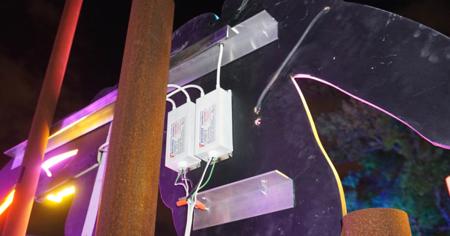
Photos by: Kayla Kling at Surreal Sea Ion Art Event
General information for what NEVER to do with electronic transformers:
- Do NOT cut the cord off of an indoor transformer – it violates UL and voids the warranty.
- Dimming in the center of a set of tubes is NOT overloading, but is energy not going through the tubes (finding the path of least resistance through capacitance coupling). Overloading the transformer causes it to flash 3 times and shut off. The solution for dimming in the middle is often through spacing of GTO and/or tubes. Sometimes it cannot be overcome – you should be using a magnetic transformer.
- Pay attention to the distance between the GTO wires where it exits the transformer body – you should never let the GTO run parallel to each other closer than this built-in gauge.
- Avoid running GTO parallel to itself and never run GTO parallel between two different transformers.
- While equal lengths of GTO are preferable, do NOT keep excess GTO on one side just to make them the same length – cut it off; shorter is always better.
- When GTO must cross, do so at right angles and not parallel.
- Three flashes of the transformer indicate either: a) open circuit / dead tube; b) overload of transformer. Test for dead tubes by process of elimination by rewiring the sign (jumping some sections out) to see if half the tubes light with the transformer and then rewire and see if the other half of the sign will light. If half the sign lights and the other side flashes 3 times, continue process of elimination until bad tube is found. If all tubes light on each half of the sign, then it is most likely overloaded.
- There are two ways manufacturers of electronic transformers rate their transformers: 1.) like Ventex does with a name that emulates the footage and performance of the same voltage magnetic transformer and 2.) the actual voltage output. When replacing a “6kV electronic transformer” it may mean you have a transformer that emulates a magnetic 6kV but actually puts out 3kV or the “6kV transformer” may be an actual 6kV output which runs the same footage as a 12kV magnetic. So, when replacing these transformers from one brand to another, be sure to compare the primary amp draw to make sure they are similar in order to get the same performance for the footage they each run.
- Ventex CL Series transformers are rated for “outdoor” but that does not mean they are waterproof.
- Ventex “indoor” electronic transformers do not have the same protective potting as the CL series, so do not use them in “damp” installations.
- Blockout paint on electrode wires can insulate the wire so much that it interrupts the series circuit especially on lower voltage electronic transformers – it will not “burn through” like a magnetic transformer and will trip off an electronic transformer like an open circuit.
- It is possible to field test electronic transformers – please see the video at ventextech.com under “Resources”.
- Any material can capacitance couple – the only insulation is distance.
- GTO and boxes:
– Do not put electronic transformers in transformer boxes or anything that looks like a box (note: a raceway looks like a long box).
– Do not use metal or plastic conduit on GTO with electronic transformers.
– Do not extend the GTO on an electronic transformer from whatever it comes with.
– Rule of thumb: Total GTO footage should not be greater than the voltage of the transformer (i.e.: 6-feet of GTO for a 6kV transformer or 12-feet GTO for a 12kV).
– “Mid-point return” style wiring is far more successful than long leads out of the electronic transformer. - True channel letters: The CL series was developed to replace PBKM style housing transformers, they will work perfectly.
- Single-Faced Cabinets: Smaller cabinets work better than larger, surface wiring works better than passing GTO in and out of the cabinet which is another opportunity to capacitance couple each time it passes through; larger pass throughs (greater clearance) work better – think porcelain housings instead of tight rubber gromets. Virtual wiring works far better than long runs of GTO from the transformer. Single transformer cabinets usually work, double transformer cabinets are less likely to work and 3 or more in the same cabinet rarely work.
- Double-Faced Cabinets: These are more difficult to make work than single-faced cabinets due to increased surface to couple to. If possible shorten wires by wiring across the cabinet instead of along each face in multiple transformer installations. Single transformers might work, double transformers rarely work and 3 or more become very unlikely.
- Double-Faced Cabinets with Perimeter Border Tubing: Unlikely to work; the perimeter border will likely be dim – this is not an overload issue (it would flash 3 times if overloaded), it is energy simply going somewhere in the cabinet and not through the neon tube.
- Raceways: Same problems as Single-Faced Cabinets, but usually worse because of multiple GTO penetrations and these are usually long signs with a lot of GTO. Single transformers might work (use virtual ground wiring method); double transformers rarely work and less likely with more electronic transformers.
- Border tubes around a building: Never works – go buy a magnetic.
For more technical support help please contact Morgan Crook at (877) 908-9193.


what does PBKM stand for, i can’t find a definition anywhere.